
SR 40 DIVERSITY - Wireless Microphone System AKG - Free user manual and instructions
Find the device manual for free SR 40 DIVERSITY AKG in PDF.

| Product Type | Diversity Receiver for Wireless Microphone System |
| Brand | AKG |
| Model | SR 40 DIVERSITY |
| Carrier Frequency Range | 710 - 865 MHz (UHF) |
| Modulation | FM |
| Audio Bandwidth | 40 - 20 000 Hz |
| Frequency Stability | ±15 kHz (from -10°C to +50°C) |
| Distortion Factor (1 kHz) | typ. 0.8% |
| Compander (compressor/decompressor) | Yes |
| Signal-to-Noise Ratio | typ. 108 dB(A) |
| Power Consumption | 110 ±15 mA |
| Power Supply | 12 - 16 V DC (via supplied mains adapter) |
| Input Sensitivity | typ. -95 dBm |
| Audio Output | Balanced XLR and unbalanced 6.3 mm jack, adjustable from microphone level to line level, max. 2 Vrms |
| Dimensions (W x D x H) | 200 x 135 x 42 mm |
| Net Weight | 470 g |
| Antennas | Two antennas, Diversity electronics activate the antenna with the best signal |
| Squelch | Fixed squelch, mutes receiver if signal too weak |
| LED Indicators | RF/MUTE, RF/OK, AF/ON, AF/PEAK, Diversity A/B |
| Cleaning | Soft cloth slightly damp, no solvents or alcohol |
| Safety | Do not open, use only supplied adapter, avoid moisture and heat |
| Supplied Accessories | 12 V DC mains adapter, rack mount kit RMU 40/div. (optional), carrying case CH 40 (optional), microphone cable MK 9/10 (optional) |
| Compliance | EN60065, EN301 489-9, EN300 422-2 |
Frequently Asked Questions - SR 40 DIVERSITY AKG
User questions about SR 40 DIVERSITY AKG
0 question about this device. Answer the ones you know or ask your own.
Ask a new question about this device
Download the instructions for your Wireless Microphone System in PDF format for free! Find your manual SR 40 DIVERSITY - AKG and take your electronic device back in hand. On this page are published all the documents necessary for the use of your device. SR 40 DIVERSITY by AKG.
USER MANUAL SR 40 DIVERSITY AKG
User Instructions. p. 11
Please read the manual before using the equipment!
1 Safety and Environment
1.1 Safety 12
1.2 Environment. 12
2 Description 12
2.1 Introduction 12
2.2 Unpacking 12
2.3 Optional Accessories 13
2.4 SR 40 diversity Receiver 13
3 Setting Up 14
3.1 Placing the Receiver 14
3.2 Rack Mounting a Single Receiver. 15
3.3 Rack Mounting Two Receivers Side by Side. 15
3.4 Connecting the Receiver to a Mixer 15
3.5 Connecting the Receiver to an Amplifier 16
3.6 Connecting the Receiver to Power 16
4 Operating Notes 16
5 Cleaning 17
6 Troubleshooting 17
7 Specifications 18
FCC Statement
This equipment has been tested and found to comply with the limits for a Class B digital device, pursuant to Parts 74, 15, and 90 of the FCC Rules. These limits are designed to provide reasonable protection against harmful interference in a residential installation. This equipment generates, uses, and can radiate radio frequency energy and, if not installed and used in accordance with the instructions, may cause harmful interference to radio communications. However, there is no guarantee that interference will not occur in a particular installation. If this equipment does cause harmful interference to radio or television reception, which can be determined by turning the equipment off and on, the user is encouraged to try to correct the interference by one or more of the following measures:
Reorient or relocate the receiving antenna.
- Increase the separation between the equipment and the receiver.
- Connect the equipment into an outlet on a circuit different from that to which the receiver is connected.
- Consult the dealer or an experienced radio/TV technician for help.
Shielded cables and I/O cords must be used for this equipment to comply with the relevant FCC regulations.
Changes or modifications not expressly approved in writing by AKG Acoustics may void the user's authority to operate this equipment.
This device complies with Part 15 of the FCC Rules. Operation is subject to the following two conditions: (1) this device may not cause harmful interference, and (2) this device must accept any interference received, including interference that may cause undesired operation.
1 Safety and Environment
1.1 Safety
- Do not spill any liquids on the equipment and do not drop any objects through the ventilation slots in the equipment.
- The equipment may be used in dry rooms only.
- The equipment may be opened, serviced, and repaired by authorized personnel only. the equipment contains no user-serviceable parts.
- Before connecting the equipment to power, check that the AC mains voltage stated on the supplied AC adapter is identical to the AC mains voltage available where you will use the equipment.
- Operate the equipment with the supplied 12-V AC adapter. Using adapters with a DC output and/or a different output voltage may cause serious damage to the unit.
- If any solid object or liquid penetrates into the equipment, shut down the sound system immediately. Disconnect the AC adapter from the power outlet immediately and have the equipment checked by AKG service personnel.
- If you will not use the equipment for a long period of time, disconnect the AC adapter from the power outlet. Please note that the equipment will not be fully isolated from power when you set the power switch to OFF.
- Do not place the equipment near heat sources such as radiators, heating ducts, or amplifiers, etc. and do not expose it to direct sunlight, excessive dust, moisture, rain, mechanical vibrations, or shock.
- To avoid hum or interference, route all audio lines, particularly those connected to the microphone inputs, away from power lines of any type. If you use cable ducts, be sure to use separate ducts for the audio lines.
- Clean the equipment with a moistened (not wet) cloth only. Be sure to disconnect the AC adapter from the power outlet before cleaning the equipment! Never use caustic or scouring cleaners or cleaning agents containing alcohol or solvents since these may damage the enamel and plastic parts.
11.Use the equipment for the applications described in this manual only. AKG cannot accept any liability for damages resulting from improper handling or misuse.
1.2 Environment
- The AC adapter will draw a small amount of current even when the equipment is switched off. To save energy, disconnect the AC adapter from the power outlet if you will leave the equipment unused for a long period of time.
- When scrapping the equipment, separate the case, circuit boards, and cables, and dispose of all components in accordance with local waste disposal rules.

2 Description
2.1 Introduction
Thank you for purchasing an AKG product. This Manual contains important instructions for setting up and operating your equipment. Please take a few minutes to read the instructions below carefully before operating the equipment. Please keep the Manual for future reference. Have fun and impress your audience!
1 SR 40 diversity

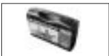
1 AC adapter, 12 V DC
Please check that the packaging contains all system components as listed above. If anything is missing, please contact your AKG dealer.
-
RMU 40/div. 19'' rack mounting kit for one SR 40 diversity receiver
-
CH 40 plastic carrying case for one complete WMS 40 system.
-
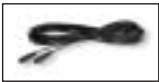
MK 9/10 microphone cable: 10-m (30-ft.)
2-conductor shielded cable w/male and female XLR connectors
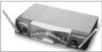
The SR 40 diversity is a stationary diversity receiver for use with all WMS 40 and microtools Series transmitters. The SR 40 operates on one fixed, quartz stabilized frequency in the 710 MHz to 865 MHz UHF carrier frequency range and features a half-rack case.
The SR 40 diversity is a diversity receiver and uses two antennas in order to receive the transmitter signal at two different spots. The diversity electronics will automatically activate the antenna that delivers the better signal.
A preset squelch will mute the receiver if the received signal is too weak so the related noise or the self-noise of the receiver will not become audible when the transmitter is switched OFF.
2.2 Unpacking
2.3 Optional Accessories
2.4 SR 40 diversity Receiver
2.4.1 Front Panel Controls
Refer to fig. 1.
Antennas: The diversity circuit will automatically activate the antenna that provides the better signal.
ON/OFF: On/off pushbutton switch. If the DIVERSITY LEDs A and B flash alternately and the RF/MUTE LED lights constantly, the receiver is ON but receives no signal.
If the RF/OK, AF/OK, and only one of the two DIVERSITY LEDs illuminate, the receiver is ON and receives signal.
When you switch the receiver OFF, all LEDs will extinguish.
RF/MUTE: This LED illuminates to indicate that no signal is being received or the squelch is active. In both cases, the audio output will be muted automatically.
RF/OK: This LED illuminates to indicate that the received field strength of the transmitter signal is high enough to drive the input.
DIVERSITY LEDs A and B: Indicate which of the two receiving antennas is active at any time.
Color code: The color of the AKG label indicates the carrier frequency of your receiver. Transmitters and receivers tuned to the same frequency are marked with identical colors.
AF/ON, AF/PEAK: These two LEDs indicate the received audio level. The green ON LED illuminating and the red PEAK LED flashing occasionally indicate optimum modulation. If none of the LEDs illuminates, the gain setting on the transmitter is too low. The PEAK LED lighting constantly indicates overmodulation.
VOLUME: This rotary control adjusts the receiver's output level from microphone to line level for matching to the input sensitivity of your mixer or amplifier.
2.4.2 Rear Panel Controls
Refer to fig. 2.
1 AUDIO OUT/BALANCED: Balanced 3-pin XLR audio output for connecting to, e.g., a microphone input on the mixing console.
AUDIO OUT/UNBALANCED: Unbalanced audio output on a 1/4" TS jack for connecting to, e.g., a guitar amplifier.
3 POWER: Input connector for the supplied AC adapter.
4 Strain Relief for the feeder cable of the supplied AC adapter.
5 Type plate with approval marks and frequency information (frequencies, frequency sets, color code).
3 Setting Up
Important!
Prior to setting up your WMS 40, check that the transmitter and receiver are tuned to the same frequency. The easiest way to do this is to compare the color codes on the transmitter and receiver.
3.1 Placing the Receiver
Reflections off metal parts, walls, ceilings, etc. or the shadow effects of musicians and other people may weaken or cancel the direct transmitter signal.
For best results, place the receiver as follows:
- Place the receiver near the performance area (stage). Make sure, though, that the transmitter will never get any closer to the receiver than 10 ft (3 m). Optimum separation is 16 ft. (5 m).
- Check that you can see the receiver from where you will be using the transmitter.
- Place the receiver at least 5 ft. (1.5 m) away from any big metal objects, walls, scaffolding, ceilings, etc.
You can either use the receiver freestanding or mount it in a 19" rack using the optional RMU 40/div. rack mounting kit.
- Unscrew the four rubber feet 1 from the receiver bottom panel.
- Unscrew the two fixing screws 2 from each side panel.
- Use the fixing screws 2 to screw the short bracket 3 to one side panel and the long bracket 4 to the other side panel. The brackets are contained in the RMU 40/div. rack mounting kit.
- Install the receiver in your rack.
To mount two receivers side by side in the same rack slot, you will need two optional RMU 40/div. rack mounting kits.
- Unscrew the four rubber feet ① from each receiver's bottom panel and remove the screws ⑤ from the rubber feet ①.
- Unscrew the two fixing screws 2 from the right-hand side panel of one receiver and from the left-hand side panel of the other receiver.
- Remove the plastic covers ③ from the side panels with the fixing screws ② still on.
- Insert one connecting strip 4 into each free slot in the side panel of the first receiver, making sure to align the hole in each connecting strip 4 with the appropriate threaded hole in the receiver bottom panel.
- Fix the two connecting strips ④ on the first receiver using two of the screws ⑤ you removed from the rubber feet.
- To join the two receivers, slide the connecting strips 4 on the first receiver through the free slots in the side panel of the second receiver. Make sure to align the hole in each connecting strip 4 with the appropriate threaded hole in the bottom panel of the second receiver.
- Fix the two connecting strips ④ on the second receiver using two of the screws ⑤ you removed from the rubber feet.
- Screw a short bracket ⑥ to the outer side panel of each receiver using for each bracket two of the screws ② you removed from the receiver side panels.
- Install the receivers in your rack.
Be sure to keep the remaining screws ⑤ for later use.
You can connect the receiver to a mixer in one of two ways:
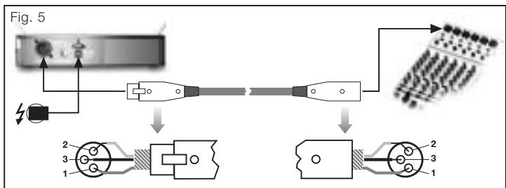
A. Use a standard XLR cable to connect the BALANCED connector 1 on the receiver rear panel to a balanced XLR microphone input on the mixer. Turn the VOLUME control on the receiver front panel all the way CCW to set the receiver output to microphone level.
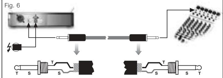
B. Use a standard 1/4'' jack cable to connect the UNBALANCED jack 2 on the receiver rear panel to an unbalanced 1/4'' line input jack on the mixer. Turn the VOLUME control 3 on the receiver front panel all the way CW to set the receiver output to line level.
Never use the two audio outputs simultaneously! This may cause signal loss or increased noise.
3.2 Rack Mounting a Single Receiver
Refer to fig.3.
3.3 Rack Mounting Two Receivers Side by Side
Refer to fig. 4.
Note:
3.4 Connecting the Receiver to a Mixer Refer to fig. 5.
Refer to fig. 6.
Important:

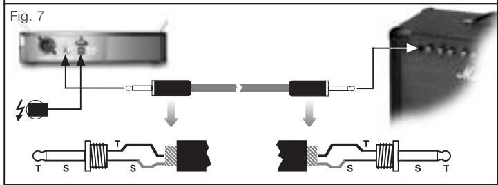
3.5 Connecting the Receiver to an Amplifier
Refer to fig. 7.
- Use a standard 1/4" jack cable to connect the UNBALANCED jack on the receiver rear panel to an unbalanced 1/4" line input jack on the amplifier.
- Turn the VOLUME control on the receiver front panel all the way CW to set the receiver output to line level.

3.6 Connecting the Receiver to Power
Refer to fig. 8.
- Check that the AC mains voltage stated on the supplied AC adapter is identical to the AC mains voltage available where you will use your equipment. Using the AC adapter with a different AC voltage may cause irreparable damage to the unit.
- Plug the feeder cable ① on the supplied AC adapter into the POWER socket ② on the receiver rear panel.
- Bend part of the feeder cable into a small bight, pass the bight through the strain relief ③ from above, and place the end of the bight snugly against the hook on the strain relief ③. Tighten the cable.
- Plug the AC adapter 4 into a convenient power outlet 5.
- Press the front panel POWER switch to switch power to the receiver ON.
If the transmitter is OFF or no transmitter signal arrives at the receiver due to other causes such as shadow effects, the RF/MUTE LED will illuminate and the DIVERSITY LEDs A and B will flash alternately.
If a transmitter signal is received, the RF/OK and AF/OK LEDs as well as one of the two DIVERSITY LEDs A or B will illuminate.

4 Operating Notes
- Switch power to the transmitter ON. (Refer to the transmitter manual.)
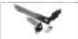
- Point the antennas approx. 45^ upward and away from the receiver.
- Switch power to the receiver ON and check the position of the VOLUME control:
Receiver connected to microphone input -> full CCW
Receiver connected to line input -> full CW
- Switch power to your sound system or amplifier on.
- Set the levels on your mixer or amplifier referring to the appropriate instruction manual or by ear.
- Move the transmitter around the area where you will use the system to check the area for "dead spots", i.e., places where the field strength seems to drop and reception deteriorates.
If you find any dead spots, try to eliminate them by repositioning the receiver. If this does not help, avoid the dead spots.
-
Make sure there will always be a direct line of sight from the transmitter to the receiver.
-
The RF/OK LED on the receiver going out means no signal is received or the squelch is active.
Remedies: Switch power to the transmitter ON and/or move closer to the receiver to a point where the RF/OK LED will come back on.
- The AF/PEAK LED on the receiver flashing frequently or glowing constantly means the transmitter signal is too strong.
Turn the GAIN control on the transmitter CCW to the point that the AF/PEAK LED will only flash occasionally.
5 Cleaning

Use a soft cloth moistened with water to clean the receiver surfaces.
6 Troubleshooting

| Problem | Possible Cause | Remedy |
| No sound. | 1. AC adapter is not connect- ed to receiver and/or power outlet.2. Receiver is OFF.3. Receiver is not connected to mixer or amplifier.4. VOLUME control on receiv- er is at zero.5. Microphone or instrument is not connected to body- pack transmitter.6. Transmitter and receiver color codes are not identical.7. Transmitter on/off switch is at “OFF” or “MUTE”.8. Transmitter batteries are not inserted properly.9. Transmitter batteries dead.10. Transmitter is too far away from receiver.11. Obstructions between transmitter and receiver.12. Receiver is invisible from transmitter location.13. Receiver is too close to metal objects. | 1. Connect AC adapter to receiver and/or power out- let.2. Push POWER switch to switch receiver ON.3. Connect receiver output to mixer or amplifier input.4. Turn up VOLUME control.5. Connect microphone or instrument to audio input on bodypack.6. Use receiver and trans- mitter with identical color codes.7. Set transmitter on/off switch to “ON”.8. Insert batteries conforming to “+” and “-” marks.9. Replace batteries.10. Move closer to receiver.11. Remove obstructions from between transmitter and receiver.12. Avoid spots where you cannot see receiver.13. Move receiver away from or remove interfering objects. |
| Noise, crackling, unwanted signals. | 1. Antenna location. 2. Interference from other wireless systems, TV, radio, CB radios, or defective electrical appliances or installations. | 1. Relocate receiver. 2. Switch off interference sources or defective appliances or use a WMS 40 tuned to a different frequency; have electrical installation checked. |
| Distortion. | 1. GAIN control on transmitter is set too high or too low. 2. Interference from other wireless systems, TV, radio, CB radios, or defective electrical appliances or installations. | 1. Turn GAIN control down or up just enough to stop the distortion. 2. Switch off interference sources or defective appliances or use a WMS 40 tuned to a different frequency; have electrical installation checked. |
| Momentary loss of sound (“dropouts”) at some locations within performance area. | 1. Antenna location. | 1. Relocate receiver. If dead spots persist, mark and avoid them. |

7 Specifications
| Carrier frequency range | 710 to 865 MHz |
| Modulation | FM |
| Audio bandwidth | 40 to 20,000 Hz |
| Frequency stability (-10°C to +50°C) | ±15 kHz |
| T.H.D. at 1 kHz | 0.8% typ. |
| Compander | integrated |
| Signal/noise ratio | 108 dB(A) typ. |
| Current consumption | 110 ±15 mA |
| Power requirement | 12 to 16 V DC |
| Input sensitivity | -95 dBm typ. |
| Audio outputs | XLR bal. and unbal. 1/4” jack: adjustable from mic to line level: 2 Vrms max. |
| Size (WxDxH) | 200 x 135 x 42 mm (8 x 5.3 x 1.7 in.) |
| Net weight | 470 g (16.6 oz.) |
| This product complies with the following standards: EN60065:1998, EN301 489-9 v.1.1.1 (09-2000), and EN300 422-2 v.1.1.1 (07-2000). | |
Page
2.4 Receptor SR 40 diversity
2.4 Receptor SR 40 diversity
H A Harman International Company
AKG Acoustics GmbH
Bodenesestraße 228, D-81243 München/GERMANY, Tel: (+49 89) 87 16-0, Fax: (+49 89) 87 16-200, www.akg-acoustics.de, e-mail: info@akg-acoustics.de, Hotline: (+49 89) 87 16-22 50, hotline@akg.com
AKG ACOUSTICS, U.S.
914 Airpark Center Drive, Nashville, TN 37217, U.S.A., Tel: (+1 615) 620-3800, Fax: (+1 615) 620-3875, www.akgusa.com, e-mail: akgusa@harman.com
For other products and distributors worldwide see our website: www.akg.com
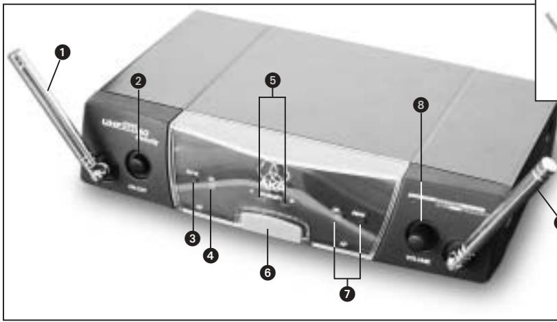
Fig. 1
SR 40 diversity
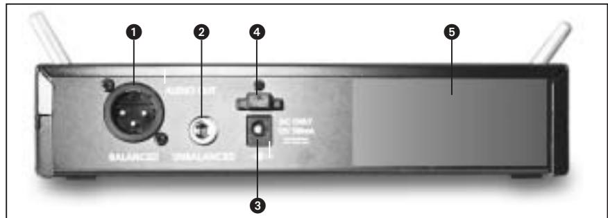
Fig. 2
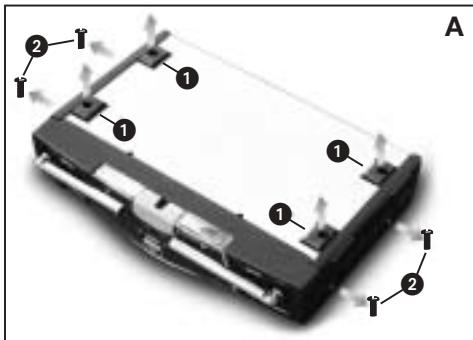
Fig. 3
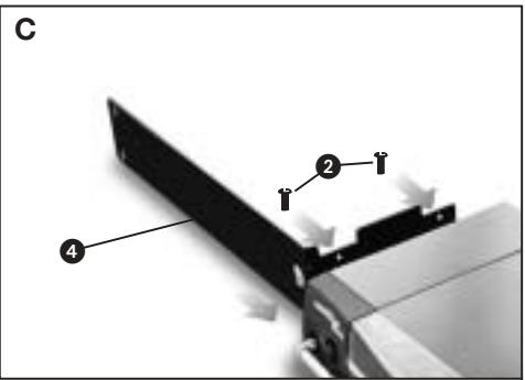
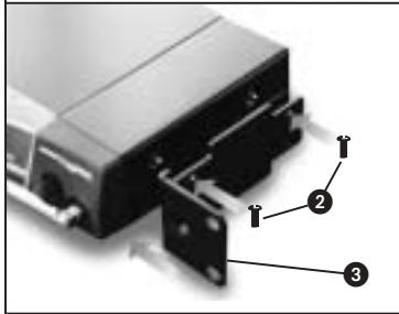

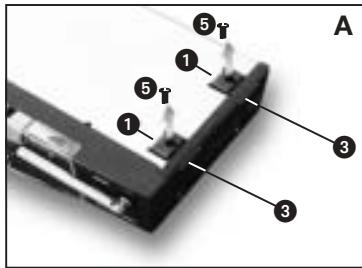
Fig. 4
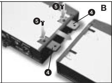
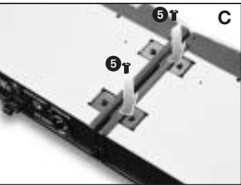
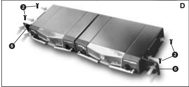
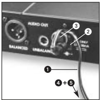
Fig. 8
- Safety and Environment
- Description 12
- Setting Up 14
- Operating Notes 16
- Cleaning 17
- Troubleshooting 17
- Specifications 18
- FCC Statement
- Shielded cables and I/O cords must be used for this equipment to comply with the relevant FCC regulations.
- Safety
- Environment
- Description
- Introduction
- Unpacking
- Optional Accessories
- SR 40 diversity Receiver
- Front Panel Controls
- Rear Panel Controls
- Setting Up
- Important!
- Placing the Receiver
- Rack Mounting a Single Receiver
- Rack Mounting Two Receivers Side by Side
- Note:
- Connecting the Receiver to an Amplifier
- Connecting the Receiver to Power
- Operating Notes
- Cleaning
- Troubleshooting
- Specifications
- Receptor SR 40 diversity
- AKG Acoustics GmbH
- AKG ACOUSTICS, U.S.
Brand : AKG
Model : SR 40 DIVERSITY
Category : Wireless Microphone System